The choice of power switching devices has steadily expanded over the years: silicon-based power MOSFETs, IGBTs, and bipolar transistors have now been joined by newer devices based on wide-bandgap (WBG) semiconductors such as silicon carbide (SiC)...

Efficiency is the name of the game in power-system design, driven by the need to better leverage available energy and deliver more power from a smaller package. Except in some specialized or extremely low-cost applications, most designs handling high voltage and current use switching technology for motor drives, inverters, and offline power supplies.
The choice of power switching devices has steadily expanded over the years: silicon-based power MOSFETs, IGBTs, and bipolar transistors have now been joined by newer devices based on wide-bandgap (WBG) semiconductors such as silicon carbide (SiC) or gallium nitride (GaN).
Another long-term design trend is the increase in power-transistor switching frequency, since it reduces switching losses and allows the use of smaller magnetic components. The adoption of WBG devices extends these advantages to power levels in the kilowatt range.
Meeting Power-Transistor Drive Requirements
A MOSFET has a significant gate capacitance that must be charged or discharged whenever the device is switched on or off. The drive circuit must supply high peak current to quickly turn on the MOSFET. Conversely, the driver is required to sink a similar amount of current to ground to turn off the device. This sequence repeats at the operating frequency of the power transistor.
Increasing the switching frequency imposes additional requirements on the driver circuitry, including operation at voltages of 5 V or lower, low propagation delay, tight matching between channels, and minimum parasitic inductance.
A complex power design often relies on a digital device such as a microcontroller to control the power delivery, calculate pulse-width-modulation (PWM) frequency, handle diagnostics, and generate the turn-on or turn-off signal. Why can’t it drive the power transistor directly?
A microcontroller does many things very well, but supplying significant current at a high switching frequency is not one of them. A typical output pin is often a 3.3-V logic signal capable of sourcing or sinking only a few milliamps—far less than required to charge the MOSFET gate capacitance in the time available. In addition, many power devices require turn-on voltages greater than 3.3 V.
A high-current gate driver between the controller output and the power-transistor input solves the problem. It combines both the level-shifting and current-drive functions. Furthermore, locating the gate driver physically close to the power switch can help minimize the effects of high-frequency switching noise on sensitive parts of the design.
Although a gate driver can be integrated into a specialized power-controller IC, a separate device allows the controller to run cooler by removing a significant source of heat. Many gate-driver ICs are available with thermally-efficient power packages that include exposed pads for heat dissipation.
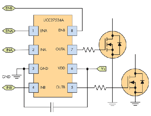
Figure shows the standard direct-drive application. The UCC27524 is a dual gate driver that can sink or source up to 5 A into capacitive loads. The two channels have matched propagation delays, which helps in applications with critical timing requirements, such as synchronous rectifiers. The inputs are compatible with TTL- and CMOS-logic thresholds, and each channel has a dedicated enable pin.
The device features fast rise and fall times of 7 ns and 6 ns, respectively, and a typical propagation delay of 13 ns with 1-ns matching between channels. It’s available in an exposed-pad DGN package.